
2 Wire Thermostat Wiring Diagram Heat Only Free Wiring Diagram
See the diagram below for the role of each wire in your system: S - Indoor and Outdoor Wired Sensors Y - Compressor Stage 1 (Cooling) Y2 - Compressor Stage 2 (Cooling) G - Fan C - Common U - Humidifier, Dehumidifier, or Ventilator control L/A - A - Input for heat pump fault O/B - Reversing valve for Heat Pump systems E - Emergency Heat
[DIAGRAM] Nand Circuit Diagram Only
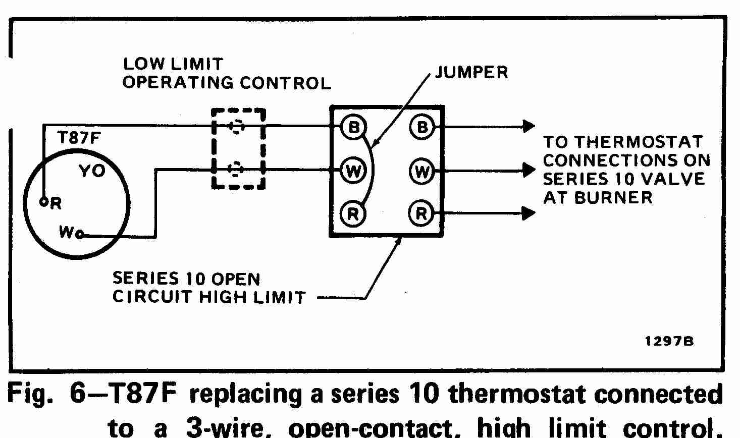
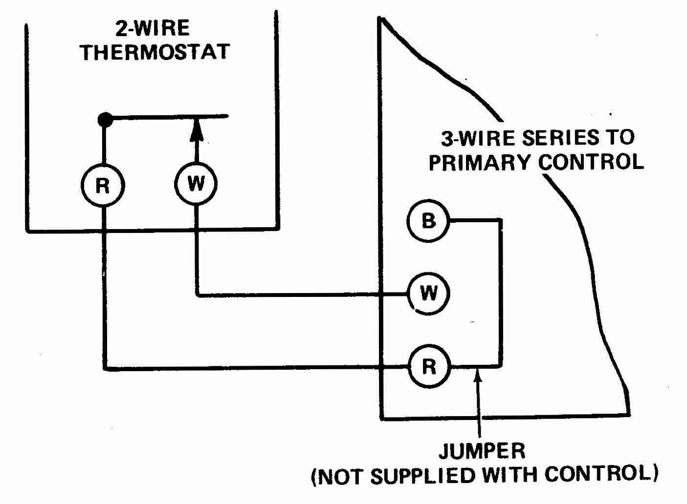
At left the thermostat wiring diagram illustrates use of a Honeywell T87F thermostat in a 2-wire application controlling a gas fired heating appliance. In the Honeywell T87F thermostat series the single pole double throw switch makes (closes) one set of contacts when the temperature falls - to turn on the heating appliance.
Honeywell Thermostat Wiring Diagram 3 Wire Cadician's Blog
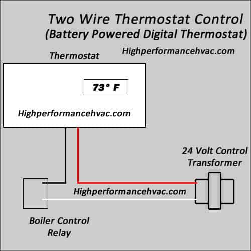
A basic two-wire thermostat can be compared to a simple single-pole switch that you will find throughout your home, only instead of you turning the switch on and off as required, a mechanical or electronic temperature controlled mechanism is the operator of the switch. The terminals are usually marked 'R' and 'W'.

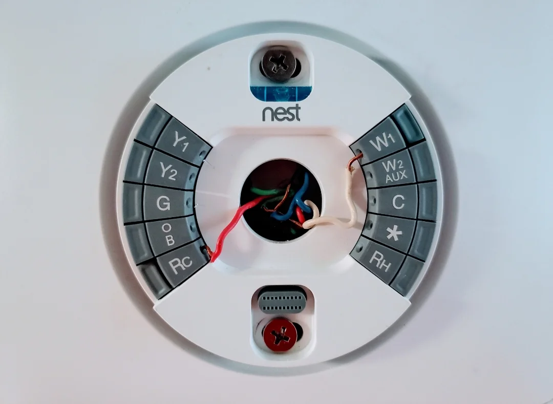
Nest Thermostat Wiring Diagram For Electric Furnace Installation
Green: The fan wire, g wire, in your thermostat will be green if you have a mini split system and will be connected to the power input in the fan of the indoor air handler units. Yellow: The yellow wires connected to the Y terminals will provide a connection to the compressor relay. You will typically find these wires in mini split systems as.
Honeywell Thermostat Wiring Diagram
At left the thermostat wiring diagram illustrates use of a Honeywell T87F thermostat in a 2-wire application controlling a gas fired heating appliance. In the Honeywell T87F thermostat series the single pole double throw switch makes (closes) one set of contacts when the temperature falls - to turn on the heating appliance.
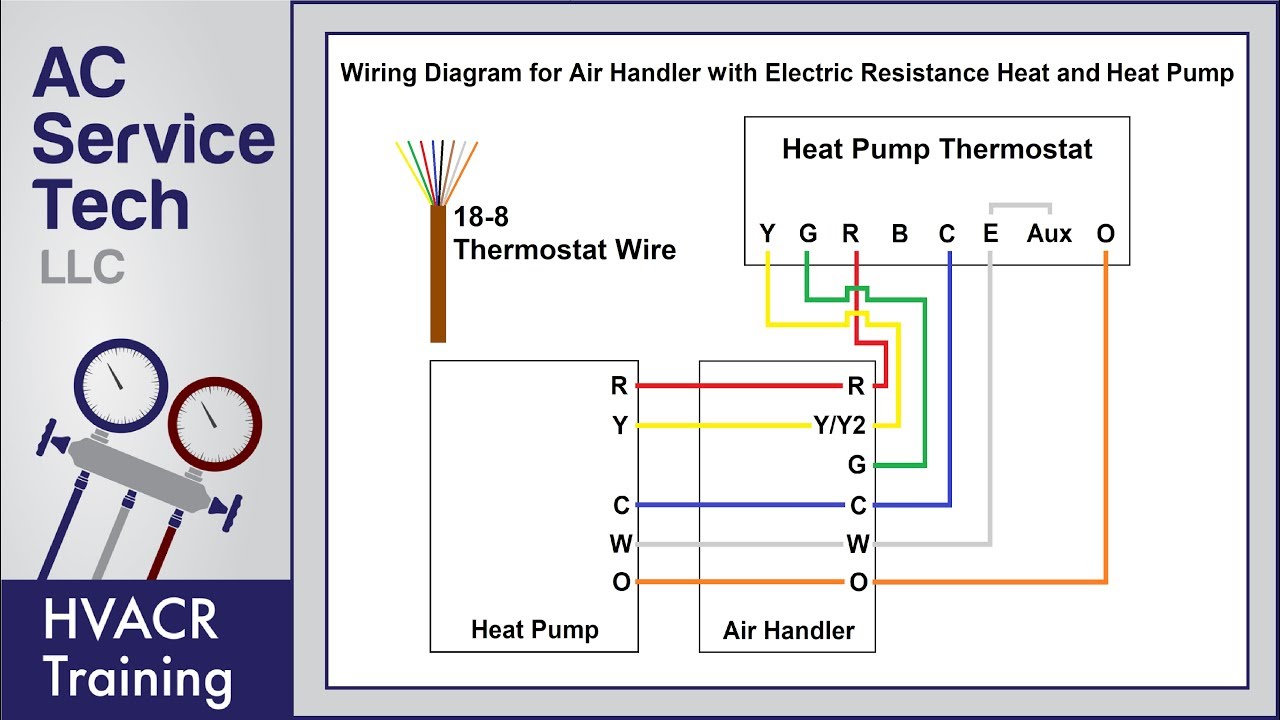
Thermostat Wiring Diagram For Goodman Heat Pump Database
The 2 wire thermostat typically consists of two wires: one for the power supply (known as the "line" or "hot" wire) and one for the load (known as the "load" or "switched" wire). These wires are usually labeled or color-coded for easy identification. Step 3: Connect the Wires
How to Wire a Thermostat Wiring Installation Instructions
Project Overview Working Time: 1 hr Total Time: 1 hr Skill Level: Intermediate Estimated Cost: $15 to $50 Unlike the low-voltage thermostats that control central heating and air-conditioning systems, electric baseboard heaters use line-voltage thermostats that are installed as part of the full-voltage circuit powering the heater.
Honeywell 2 Wire Thermostat Wiring Diagram Heat Only 4K Wallpapers Review
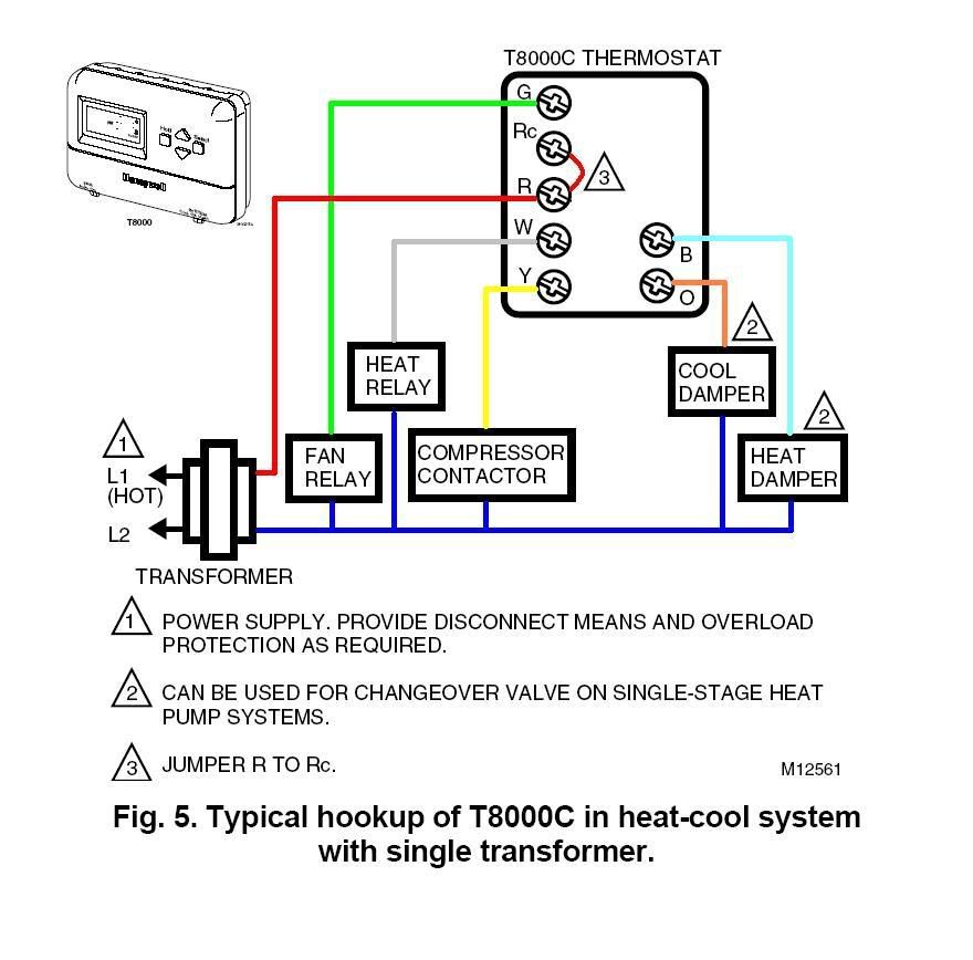
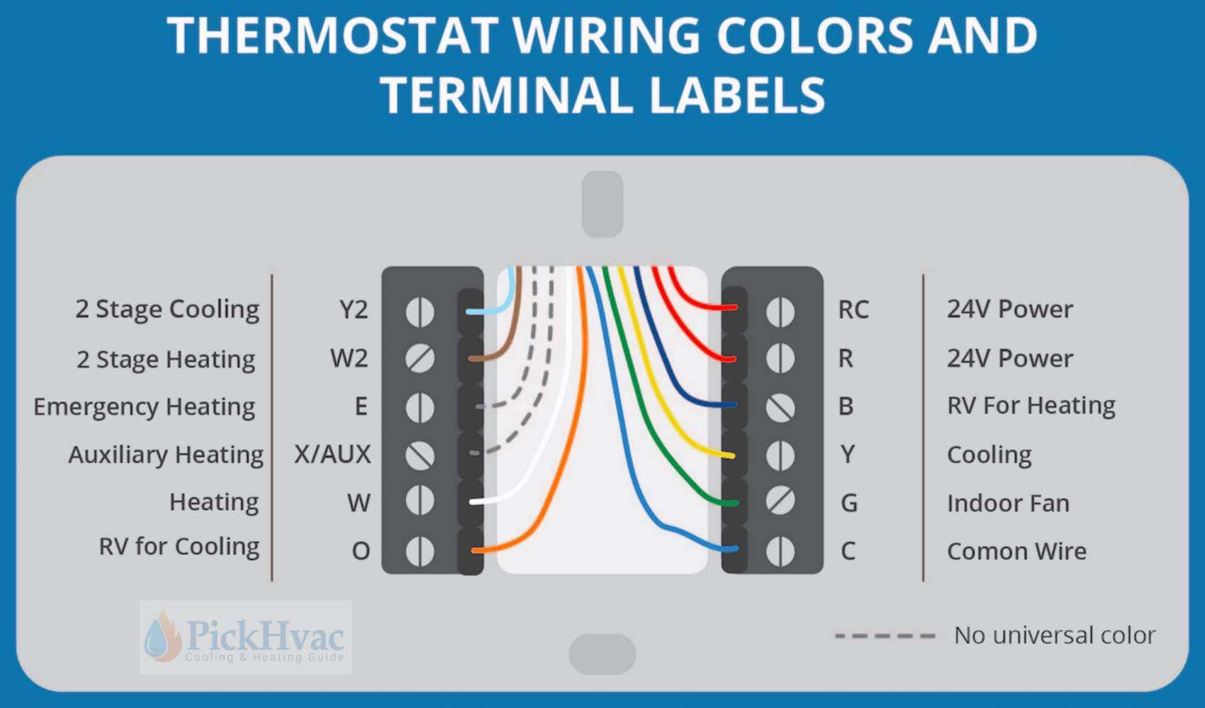
Air Conditioner Thermostat Wiring Details and Color Code. R Terminal is Connected to the Red Wire or R Wire - this is 24-volt power for the thermostat and controlled devices. Origin is the control transformer and then the R Terminal. G Terminal is connected to the Green Wire or G Wire - This is for the blower fan in the air handler.

Modine Heater Thermostat Wiring Diagram 2 Pin Marco Wiring
Like a light switch, a two-wire thermostat has one "line" terminal for a hot wire and one "load" terminal to power a single appliance. There are no terminals to control fans, compressors, or heat pump reversing valves, which are common components of more sophisticated HVAC systems.

2 Wire Thermostat Wiring Diagram Heat Only Free Wiring Diagram
Most two-wire systems are primarily used for line voltage thermostats that provide heating only and feature one red and one white wire. Red wires or R-wires, labeled either as "R", "Rc" or "Rh" on the terminals are for their power source and white wires or W-wires are for heating.

2 Wire Thermostat Wiring Diagram Heat Only Free Wiring Diagram
To properly wire a 2 wire thermostat, you will need to connect the "R" wire to the power terminal on the thermostat and the "W" wire to the heating terminal. It's important to follow the wiring diagram provided by the thermostat manufacturer to ensure the correct connections.
Room thermostat wiring diagrams for HVAC systems
At every stage, we will point out what 2 wire or 5 wire thermostats are used to wire, for example, to get a bigger picture of where those color wires go and how they enable the functions of air conditioners and furnaces. In all cases, we will use this basic Honeywell thermostat for reference:

Out Of This World Honeywell Programmable Thermostat Wiring Diagram 2008
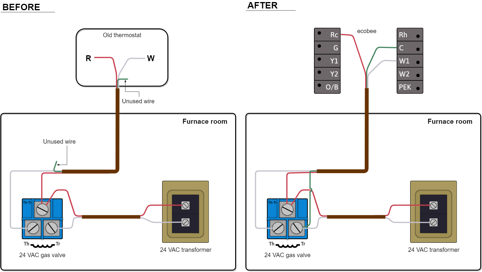
Toggle Is My HVAC System a 24-volt System? 3 Method to Wire a Thermostat #1 Replace the thermostat wire for wire: #2 Locate the wiring connections in the furnace or air handler: #3 Use standard wiring colors to connect the thermostat: Common Thermostat Wiring Options - 2 Wire to 8 Wire Thermostats 2 Wire Thermostat Wiring 3 Wire Thermostat Wiring

Wiring Diagram Carrier Thermostat Wiring Draw
1 Thermostat Wiring Tips To install your unit, you'll need to connect the correct wires to the corresponding terminals on the back of your new thermostat. Here is the industry standard color code for thermostat wires used for most systems: The W wire is connected to your heating system.
Wiring Diagram For Thermostat Lexia's Blog
Overall, a 2 wire thermostat wiring system offers a convenient and efficient way to control the heating in your home. Its simplicity and ease of installation make it a popular choice among homeowners looking for a straightforward and effective solution. So, if you're after a hassle-free heating control system, consider opting for a 2 wire.

Double Pole Line Voltage Thermostat Wiring Diagram Wiring Diagram Schemas
When it comes to low voltage systems, a 2 wire thermostat is usually known as a "heat only thermostat" and is used for systems like a gas furnace (with only a heating option). A 2 wire thermostat can not be used for HVAC systems with a cooling option, or heating systems with multi stages or a heat pump. Wiring & Color Code